Carolo Cup 2022 Presentation
Hello my name is David and together with Max, we are going to represent team galaxis today during this presentation.
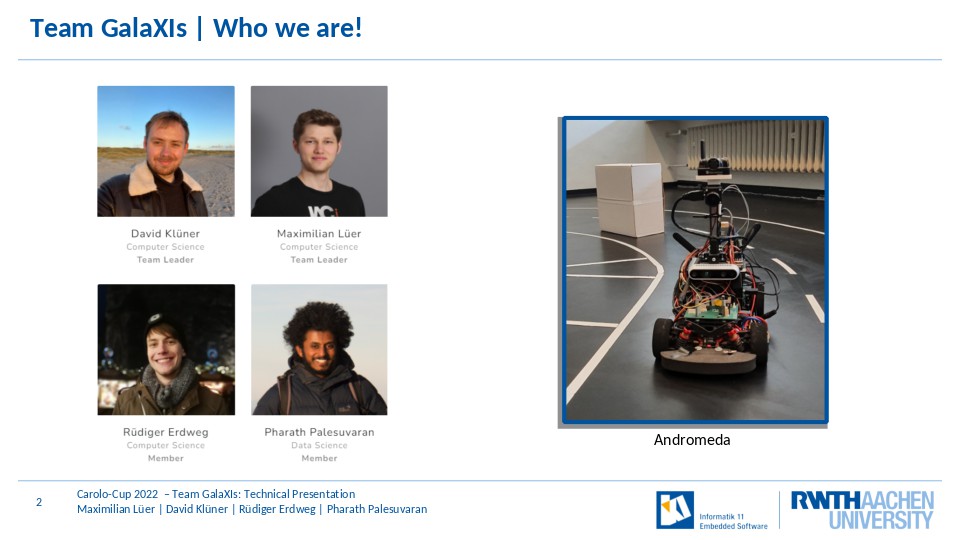
Lets first talk about who we are: We are a small team of four members and this is our car andromeda.
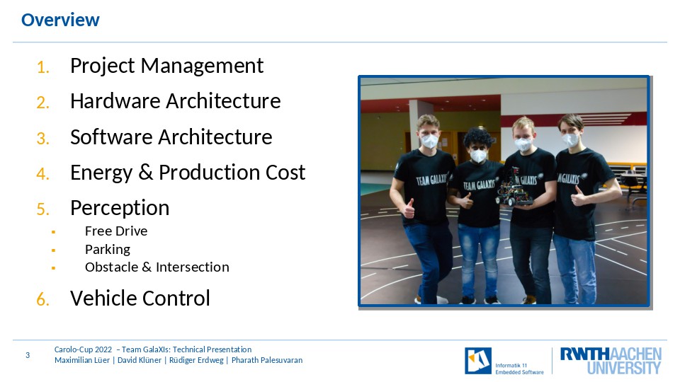
Our following presentation follows the categories of the evaluation sheet. So we are going to talk about our Project Management, our Hardware and software architecture, the energy and production cost of our vehicle, our perception systems and finally our control algorithms.
Project Management

Lets start with our Project Management.
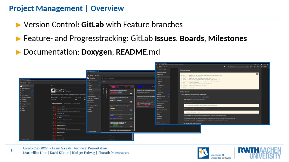
We first want to give an overview over the tools we use for our Project Management.
To Track Issues and the Progress of developments we use: Gitlab with Feature branches, Gitlab Issues, Gitlab Milestones and Boards
and we document our code using comments in Code, Doxygen and Readmes.
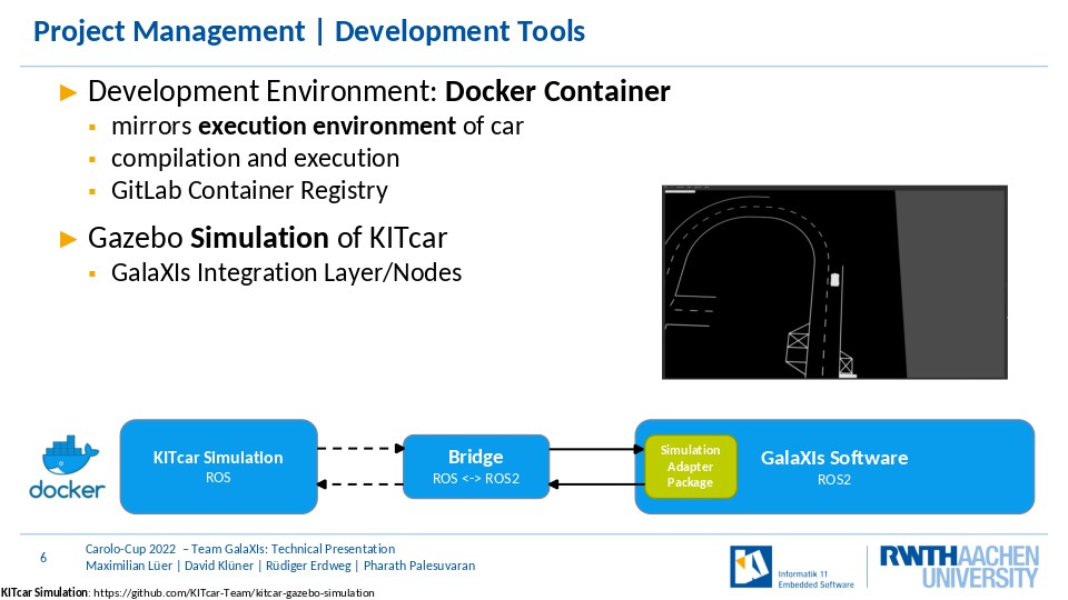
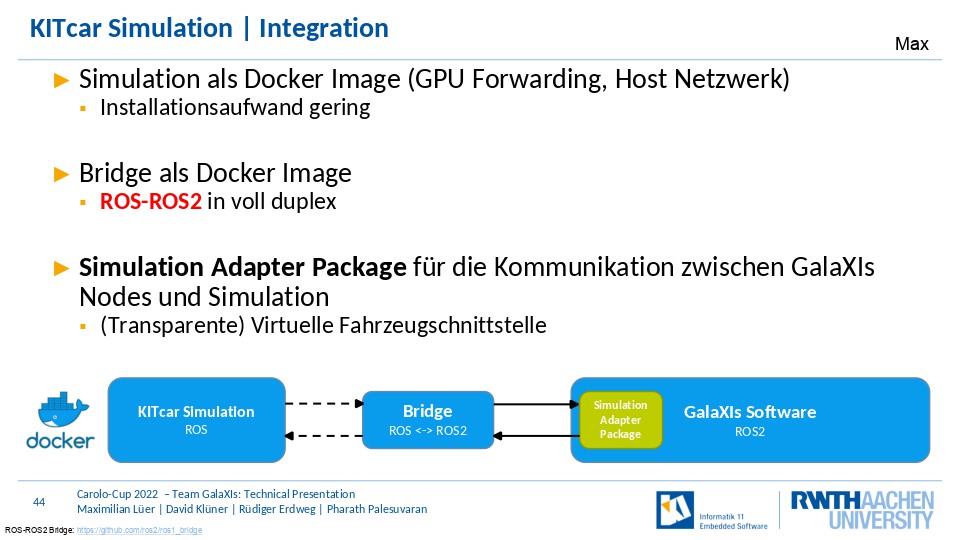
To develop a new feature for our vehicle, we use our Docker container, which mirrors the environment on the vehicle. This allows us to compile and test our code on our own machines under similar conditions like those on the vehicle, without the need to access the vehicle.
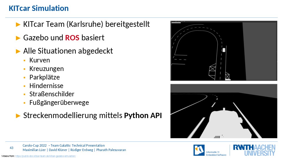
We also use Kitcars Gazebo simulation for testing, which we have integrated into our software using the ROS-ROS2 Bride and our Simulation Adadpter Package, which ensures that the same software can run on our vehicle as well as in the simulation.
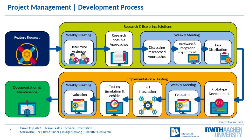
A crucial part to our project management is our development Process.
For us this process begins with a feature request. This request is then assigned to a team member, who then researches possible approaches.
The possible solutions are then discussed among all team members in our next weekly meeting and the requirements on our existing software and hardware are determined.
Once a solution has been chosen, the assigned team members develop a prototype and we discuss how well this prototype works and what might still need to be done.
If the prototype delivers acceptable performance, it is integrated with out software and tested in simulation and on the vehicle.
Finally the implementation is documented.
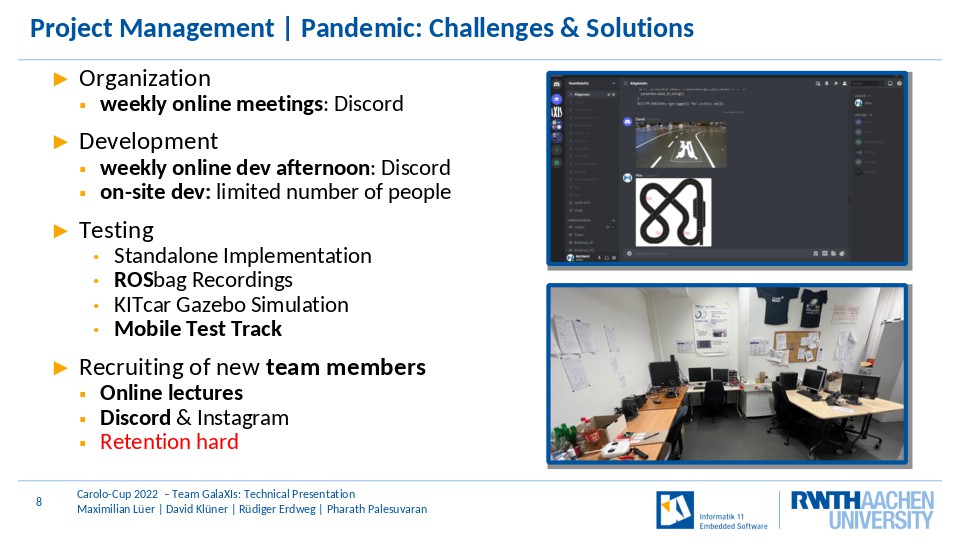
As noted before we use weekly meetings, before the pandemic these were in person in our room and now these take place online on discord
Before the pandemic our main development was done at our team room.
But as this is now not possible, most of our software is developed online in weekly online development afternoons;
Hardware developed and on-site work can currently only be done by one person in our room.
To cope with these restrictions we expanded our ability to test without the car, by using our modular architecture to test nodes in isolation.
We also made extensive use of ROSBag recordings and the kitcar gazebo simulation to be able to continue to develop under these limitations.
Finally we also used our mobile larger test track to be able to keep a larger distance to other team members
During the pandamic, we also found new ways to reach students by visiting online lectures and using discord and instagram but converting interested students into full team members was a problem.
Working remotely was not able to generate the same enthusiasm in theses interested students as working in person on the car could and thus we lost students.
This problem was especially pressing when we hadnt integrated the simulation with our software, as testing was very limited back then.
Hardware Architecture

In the next section, we are going to present the hardware architecture of our car.
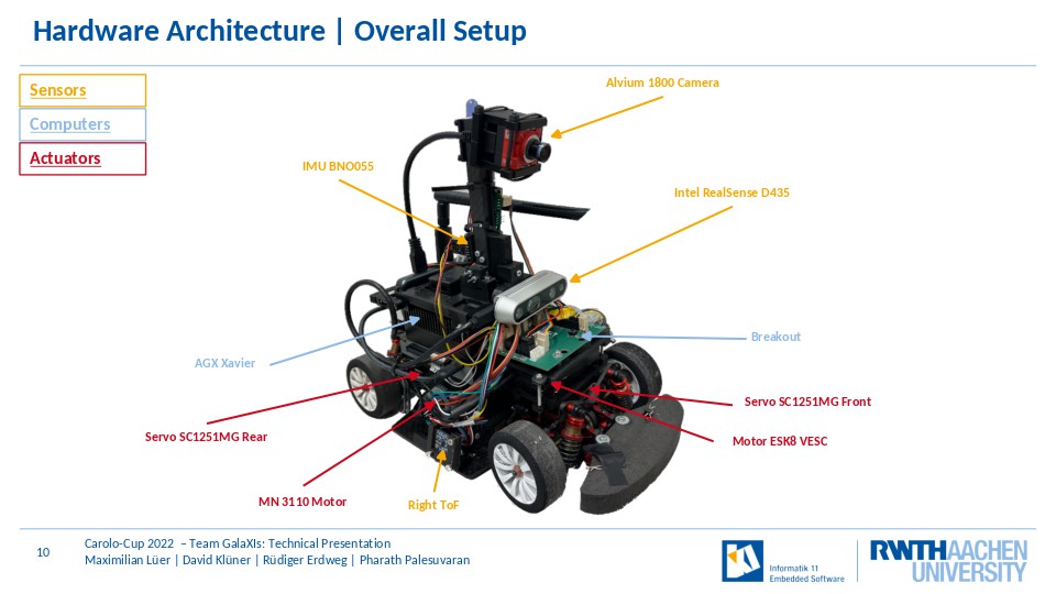
Due to our small team size and the addition problems of procuring parts during the pandemic, we deceided to make only necessary changes to the car and focus on software
Our car has two steerable axis and has a very small turning circle to aid with parking. It also has all wheel drive using a single motor .
For sensing the environment, it is equipped with a regular RGB Camera and a Depth Camera, an IMU and TOF sensors.
For autonomous operations it is. Equipped with two computing units.
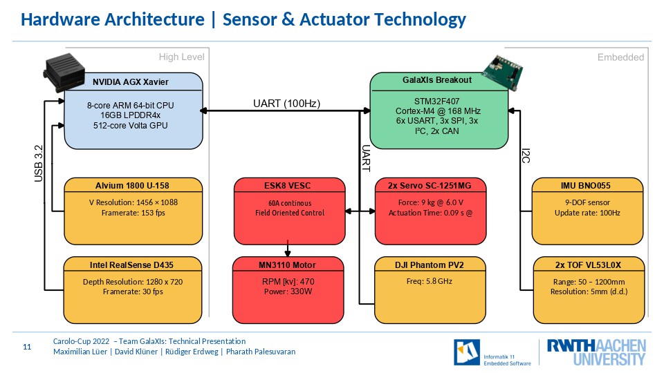
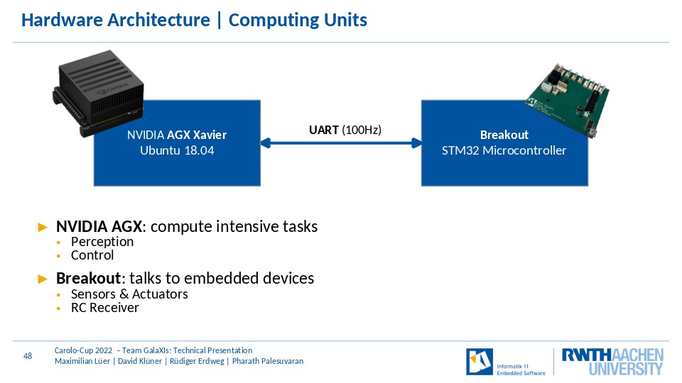
Our main computing unit, the Nvidia AGX Xavier is responsible for compute intensive tasks like environment detection, planning and high-level control.
Our secondary compute unit, the STM32 on our Breakout board communicates with embedded sensors and actuators, as well as our rc receiver.
The communication between these two computers operates at 100Hz using uart.
We deceided to use the Nvidia AGX Xavier in contrast to a less powerfull Computer because we wanted performance overhead and the option to deploy more deep learning solutions.
We also think that the use of two systems offers significant advantages, as this two system architecture allows us to swap main compute units while only having to reimplement the single UART Interface.
Software Architecture

In the next Section we are going to introduce our Software architecture.
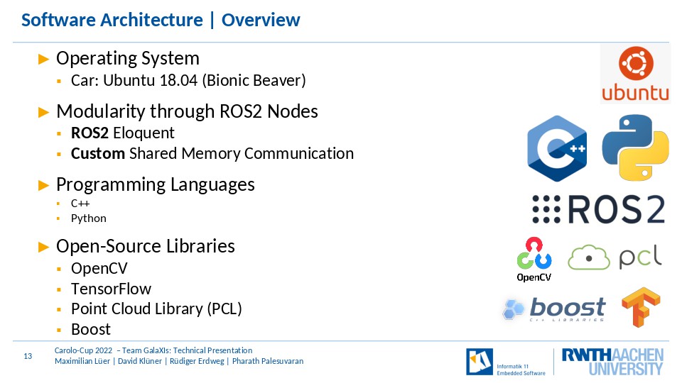
Our car runs Linux4Tegra, which is a modification of Ubnutu 18.04 by Nvidia.
Our software is split into ROS2 Node and we use ROS2 Eloquent specifically because it is the newest version available for the AGX.
Thanks to ROS2 our software is highly modular and it is easy to exchange nodes or reuse them. ROS2 also allows us to run a single node on a PC for debugging purposes while the remaining software stack runs on our car
However as ROS2 presented us with poor performance when dealing with python nodes and large, high frequency message, we also use a custom shared memory communication channel between certrain software components.
Alternatively to this modular, distributed architecture, a monolithic architecture could be used, but we believe this would present us with a significant number of disadvantages, like more difficulty testing, debugging and even developing individual functions.
We also use a number of open source libraries, like OpenCV for computer visionn, Tensorflow for deep learning and more.
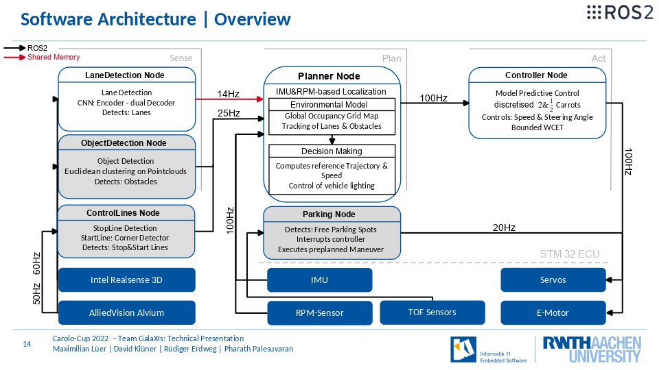
This slide contains an overview over all nodes in our vehicle.
The nodes can be roughly divided using the sense plan act paradigm, where the sense nodes are responsible for perceiving the environment, the planning nodes plan our reference trajectory and parking maneuvers and our act node, turns the reference trajectory into a driven path.
Not all nodes are active all the time, the grey marked nodes are for example not active in certain disciplines during the competition and this allows us to save the resources that these nodes might consume.
Energy & Production Cost
Next we would like to talk about the cost of our vehilce and its energy efficiency.
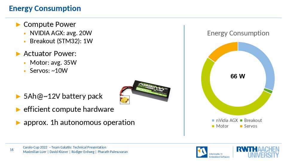
Our car consumes about 66Watts on average and this translates to approximately one hour of autonomous operation on a 5 Ampere hour battery.
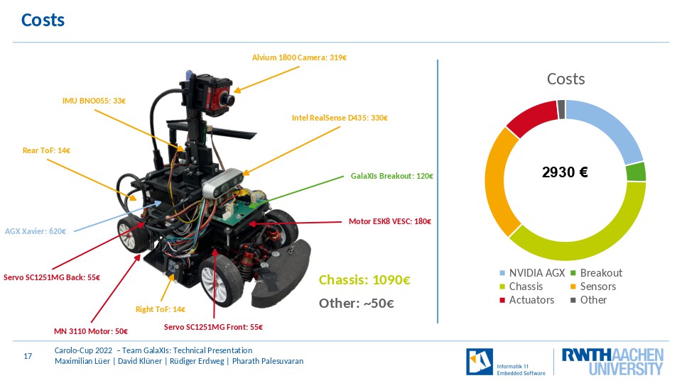
Our car costs in total 2930 Euros and the majority of this costs comes from the chassis, the Nvidia AGX and our cameras.
Perception
Free Drive

Now lets talk about the perception of our vehicle and our lane detection algorithm.
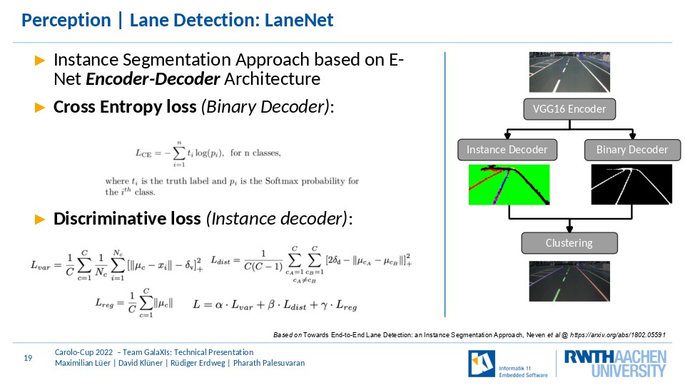
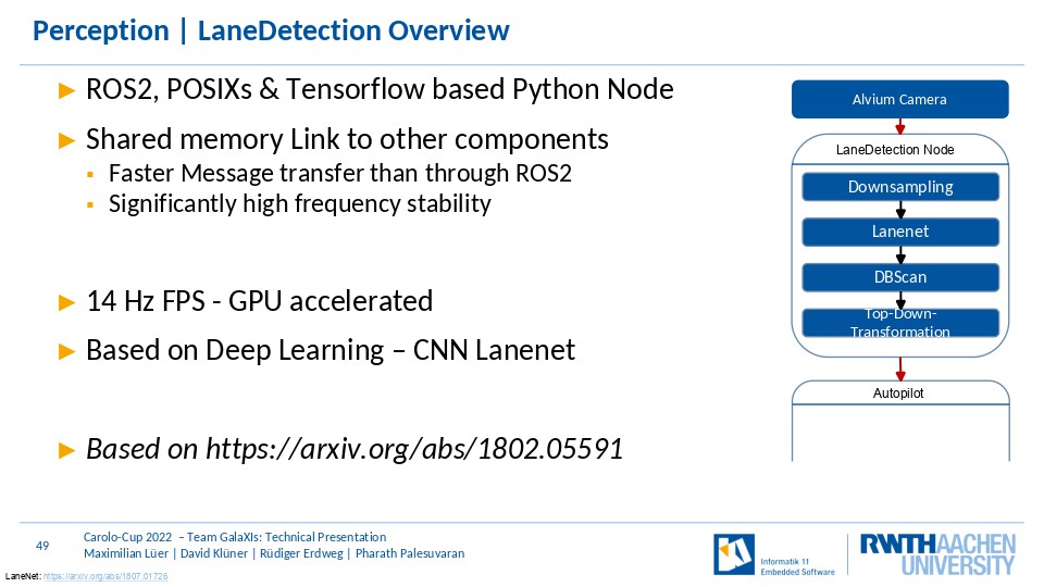
For lane detection we use a deep learning approach.
The Network is called Lanenet and is based on the the paper we have referenced in the lower right.
It computes an instance segmentation image using a single VGG16 shared encoder, that computes features for the two Decoders.
The Instance decoder is trained with discriminative loss to ensure better seperation in embedding space between the different lanes.
While the Binary decoder is trained using regular cross entropy loss to distinguish between lanes and background, this is done to deliver higher spatial precision than the instance decoder could deliver alone.
Finally the result of the instance decoder is postprocess using a clustering in the embedding space of the instance result and finally the two results are combined
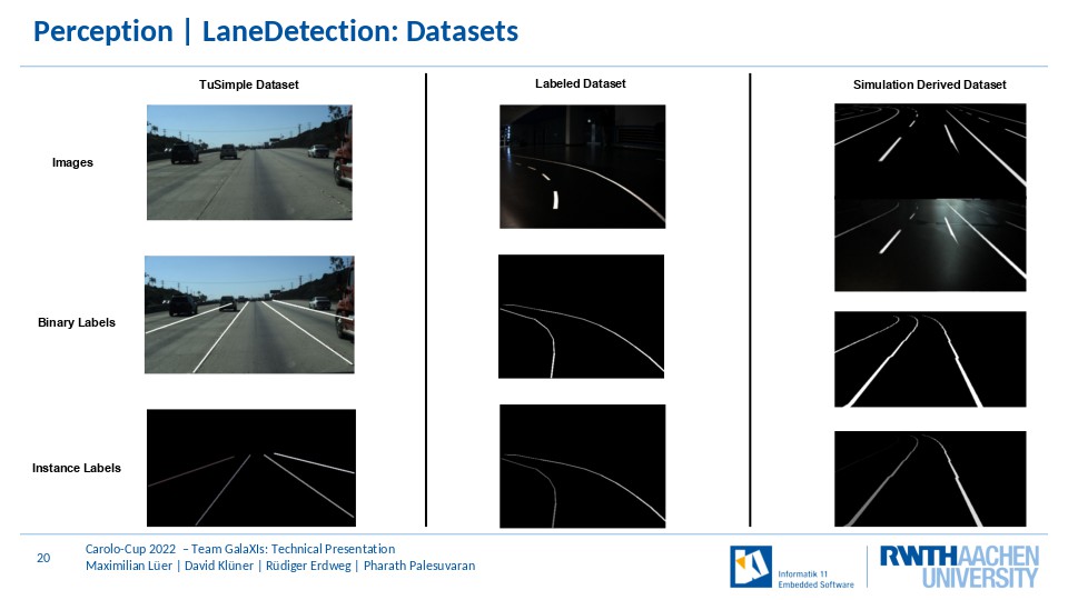
For training of the Network we used three different datasets.
The first is the publicly available tusimple dataset, our own dataset that we manually annotated and a simulation derived dataset.
Our simulation data is heavily augmented, by swapping the background of images, flipping them, changing. the brightness levels and more.
We used deep learning here as it yielded higher robustness to changes in illumination, angle of the car to the lanes and missing lane markings in comparison to a classic computer vision approach.
We specifically trained for missing lanemarkings using real world data, but also specifically using simulation derived images as we could create these situations easily there
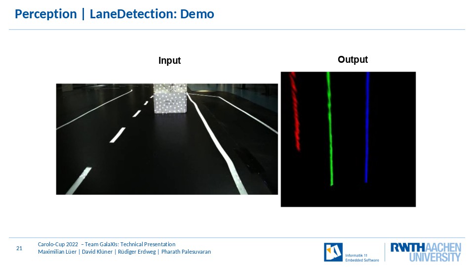
This yields overall good results and allows the network to interpolate missing lanemarkings, as you can see in the short video above
Parking

Lets talk about Parking and here the perception in particular.
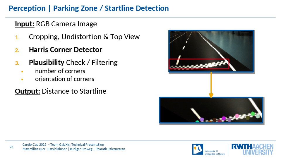
In order to start the parking pipeline, the car continously scans the route ahead for a startline. Here, the images of the front facing camera are cropped, undistorted and transformed to top view perspective. Then, the Harris Corner Detection Algorithm of OpenCV is applied to detect corners on the cropped image that potentially belong to the startline. If there are enough corners on a similar height, a startline is assumed to be in front of the car.
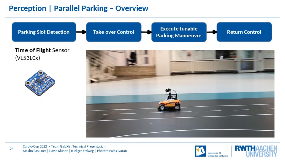
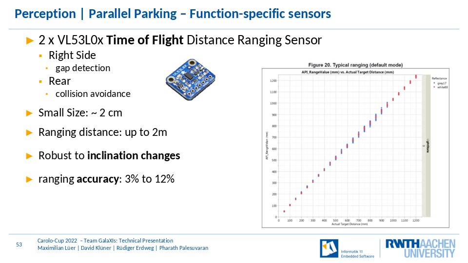
After the startline is detected, the parking node is enabled which searches for a parallel parking slot large enough for the car. Here, the right Time-of-Flight Sensor is used to estimate the width of the parking slot. If a suitable parking slot is found, the parking node takes over the control of the car. Based on the current distance to the right lane marking, the scalable parking manouvre is executed. Afterwards the control of the car is returned.
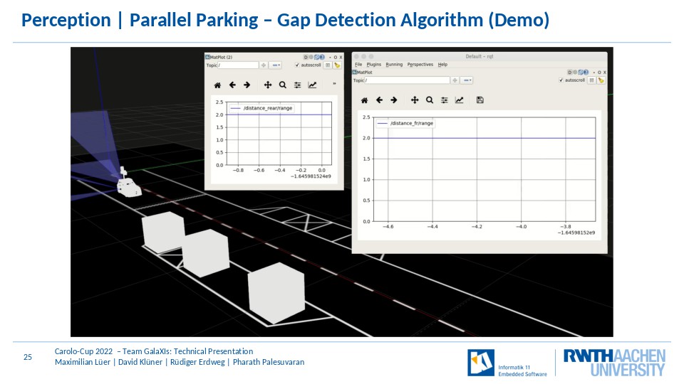
In order to give you more detail into the gap detection algorithm you can see here an excerpt of the simulation with distance information of the ToF sensors. The parking node monitors the right distance to the next object while passing by the parking slot. Based on this information and the current speed, the car is able to estimate the parking slot width and if it is large enough, the parking node takes over control and replays the manouvre based on the current distance to the right lane marking. While parking, the rear tof is used for collision avoidance with the obstacle behind.
Obstacle

Lets come to the perception of obstacles.
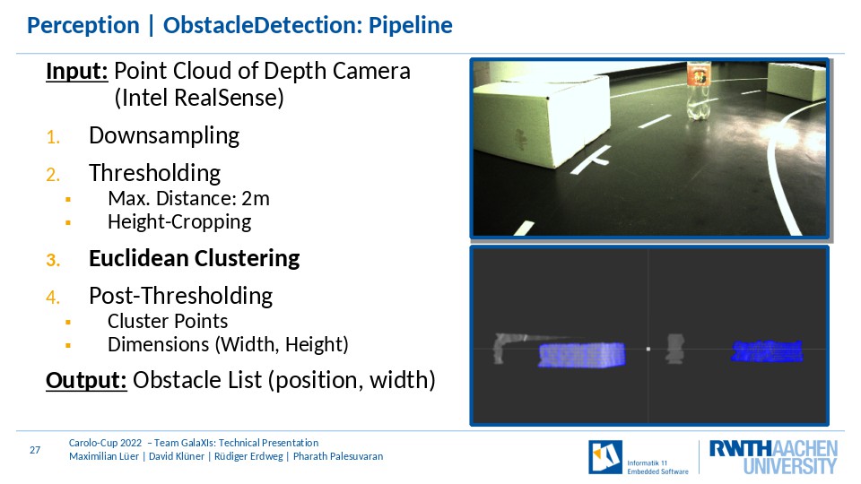
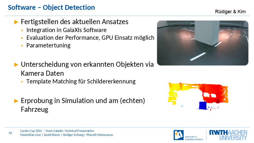
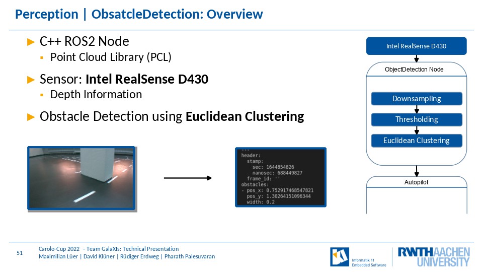
In order to detect obstacles, the Intel RealSense camera provides depth information about the frontal environment of the car. In a first step, the depth information of the RealSense camera are downsampled and then thresholded. Here, depth information about objects that are farther away than 2 meters or higher or lower than specified height thesholds are discarded. Then, euclidean clustering is applied and afterwards a post-thresholding eliminates disruptions in the depth information as well as other objects that are too large. Finally, relevant obstacles are appended to an obstacle list containing position and width information about the obstacles. The list is sent via the ROS2 network.
Intersection

At next we have a look at the perception of intersections.
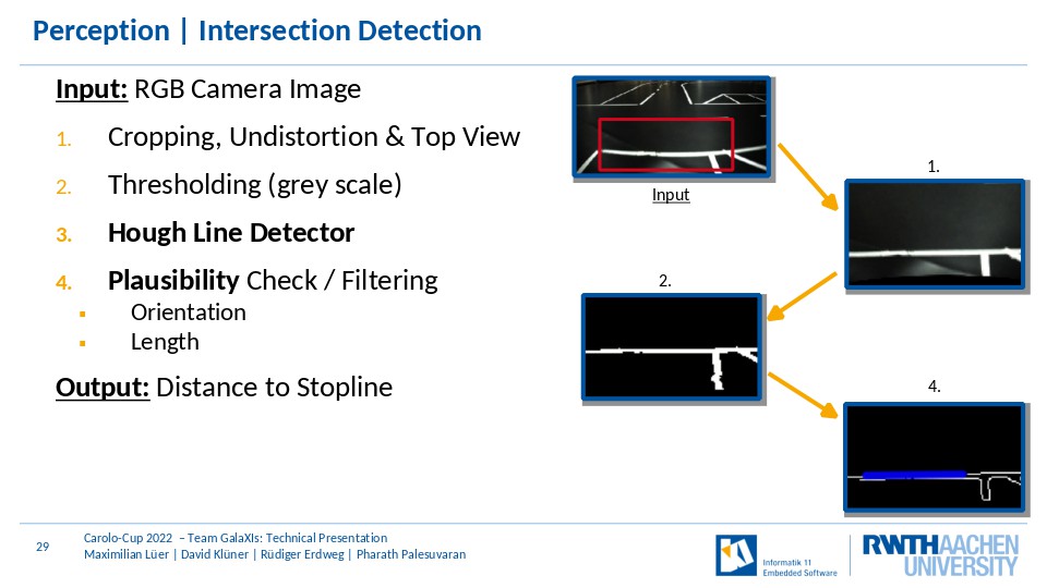
As for the StartlineDetection, the camera images are the input for the pipeline. In order to increase the performance and ignore irrelevant information, the camera image is cropped in a first step. Then, it is undistorted and transformed to top view. A grey-scale thresholding is applied to reduce disruption. Based on this, the hough line algorithm is used to detect straight lines on the image. Finally, the detected lines are checked if the properties such as length and longitudinal offset fit to a stopline and then the car distance to the stopline is calculated and returned.
Planning

Finally lets talk about the control of our car.
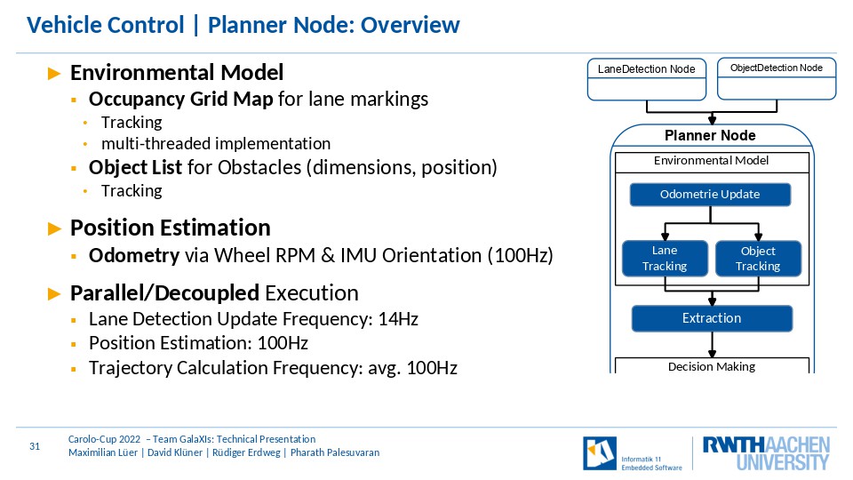
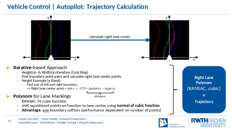
The Planner Node consists of an environmental model and the decision maker. It receives environmental information, inserts it into the model and calulcates the reference trajectory and speed of the car. The environmental model consists of an occupancy grid map holding the lane markings and an object list holding the position and width of the obstacles and tracks them. Furthermore, it esimates the location of the car by integrating the information of the RPM sensor and IMU Orientation. In order to increase the trajectory updates, the planner operates in a parallelized fashion. Thus the trajectories can be updated at a frequency of 100Hz and are not bound to the comparably slower lane detection.
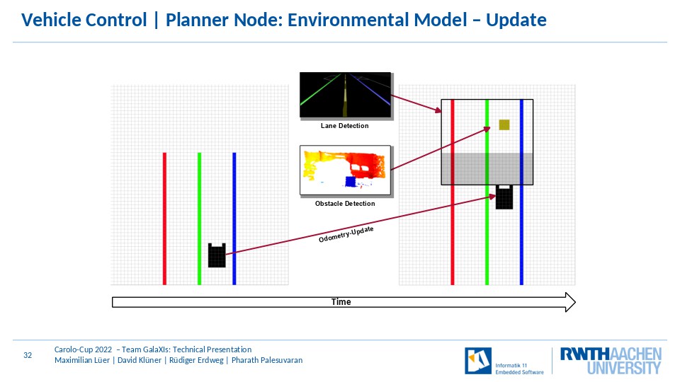
At next, we provide you a quick overview about how the environmental model is updated. At the left side you can see a visualization of the grid map and the estimated position of the car. Now, new information about the lanes, obstacles and the rpm and imu sensors are coming in. They are inserted based on the new estimated position of the car on the map.
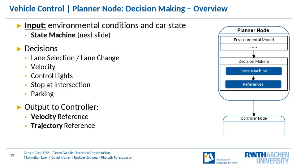
Lets talk about the decision making of the car. Input here are the environmental conditions as well as the current state of the car provided by the state machine which we present to you just after this slide. The following decisions must be made: on which lane the car should drive at which velocity and which control lights such as left, right or brake indicator should be enabled. Furthermore, it decides how long the car stays at the intersection and when it starts the parking operation. Output is then the reference trajectory and velocity for the controller.
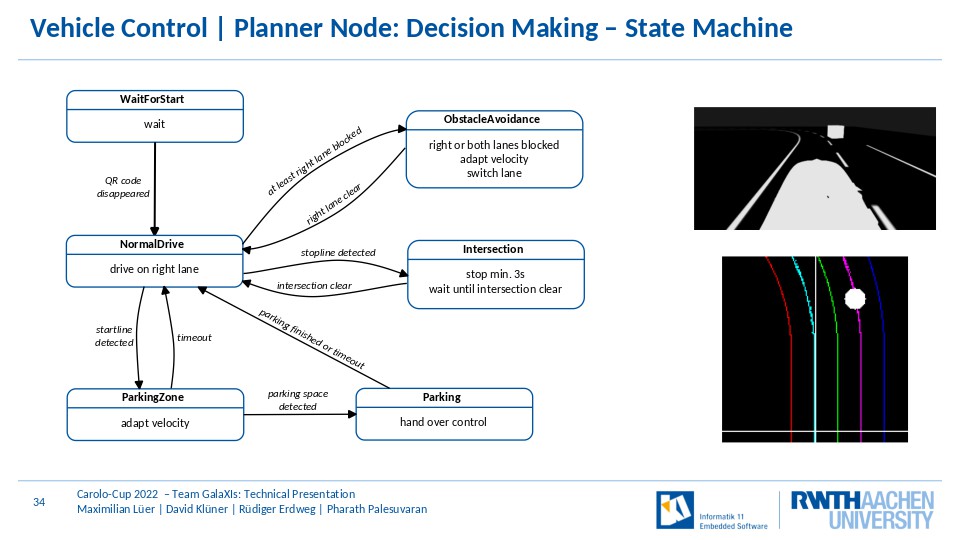
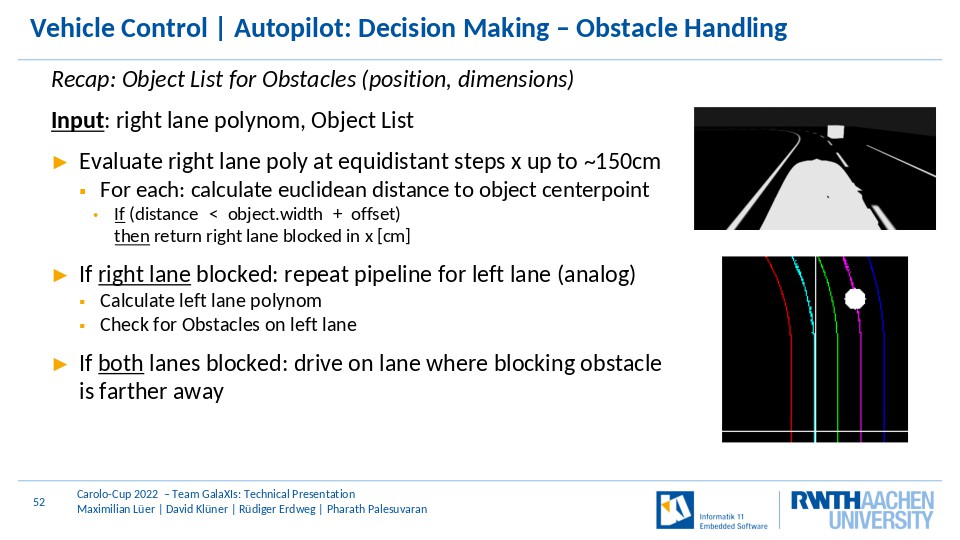
As already mentioned, the decision making is based on a state machine. In NormalDrive, the car is driving on the right lane. If an obstacle crosses the current trajectory that is set to the lane center of the right lane, the machine enters the obstacle avoidance state where the velocity is adapted and the lane is chosen based on the current blocked lane. If the right lane is clear again, it returns to normal drive. If a stopline was detected, the car stops at the specified distance to the stop line, waits at least three seconds and returns to normal drive if no obstacle is present. For the case, the start line is detected, the parkingzone state is entered in which the parking node is activated that searches for a suitable parking slot. If one is found, the control is handed over to the parking node and after parking the state enters normal drive again. In the parkingzone and parking state, the planner stops the parking if it takes too long to finish.
Control
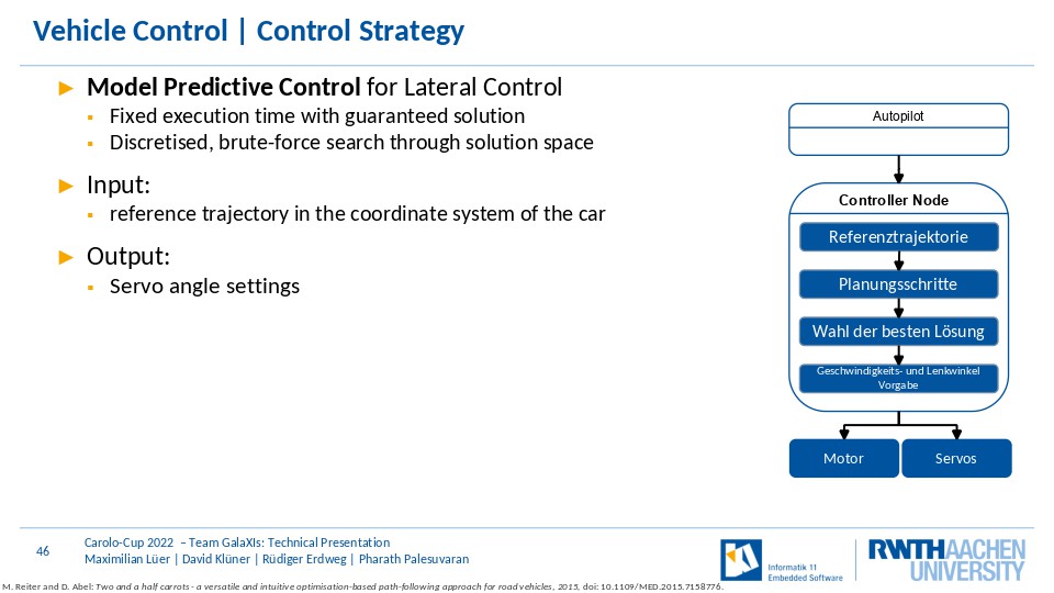
Lets have a look at the lateral and longitudinal control of our car. The speed of the car is controlled by a PID controller. For lateral control, the car consists of a model predictive controller. Input for the lateral control is the reference trajectory and the current speed that is measured by the RPM sensor of the car. The MPC is build upon a brute-force based approach whereby trajectories, that were calculated by applying constant yaw rates, are compared with the reference trajectory. The best found trajectory then defines the front servo setting of the car.
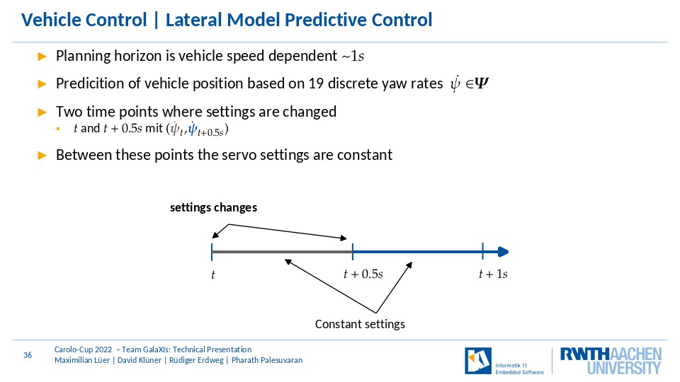
Lets have a deeper look to the lateral MPC: The controller has a speed-based planning horizon of about 1s. There are 19 discrete yaw rates (0 degree/s, and additionally 9 for each direction). Furthermore, there are two time points, timepoint t and t+0.5, where the yaw rates can be changed. Between these and after timepoint t+0.5 the yaw rate is constant.
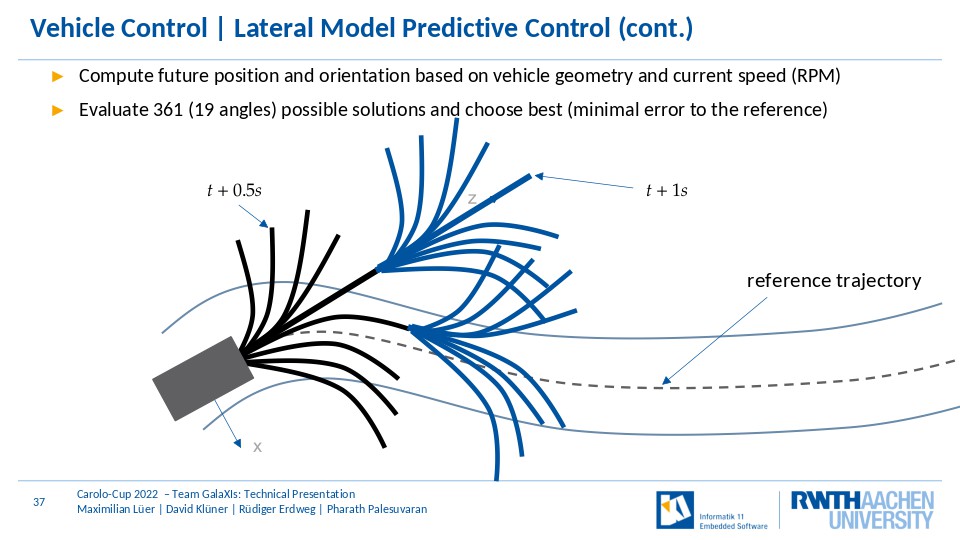
So, what is the controller doing then? For all possible yaw rate pairs, meaning 361, the future positions and orientations are calculated and compared with the reference. Then, the best yaw rate pair is chosen. The first yaw rate then defines the applied servo setting. Lets look how the pairs are evaluated.
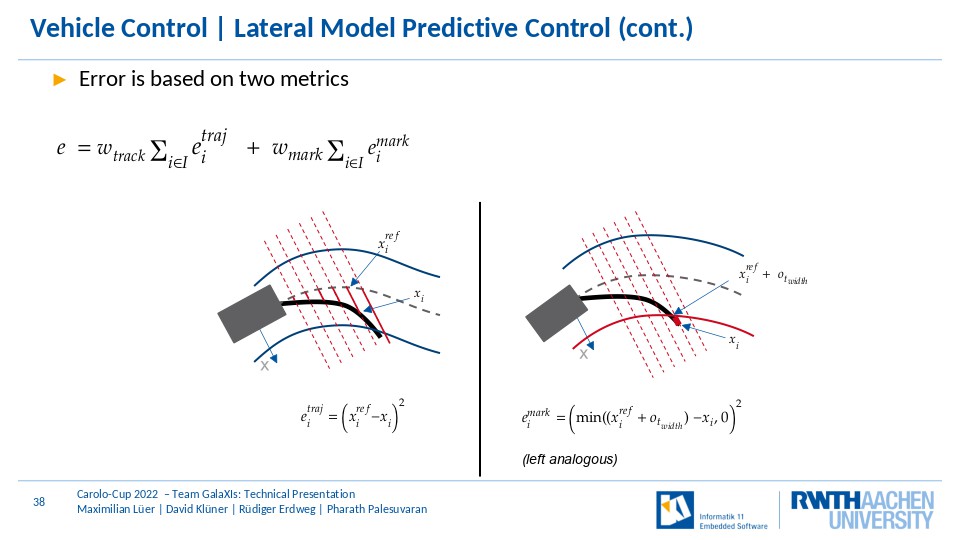
For each trajectory based on the yaw rate pair, an error based on two metrics is calculated. The first metric is the squared lateral misalginment and the second metric penalizes trajectories outside the track, meaning those trajectories who cross the right or left lane marking.
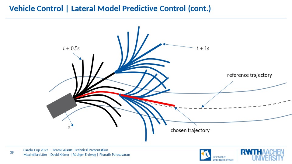
The yaw rate pair defining the trajectory with the smallest error is then chosen as the best and the yaw rate of the first time period is translated to the corresponding front servo steering setting.
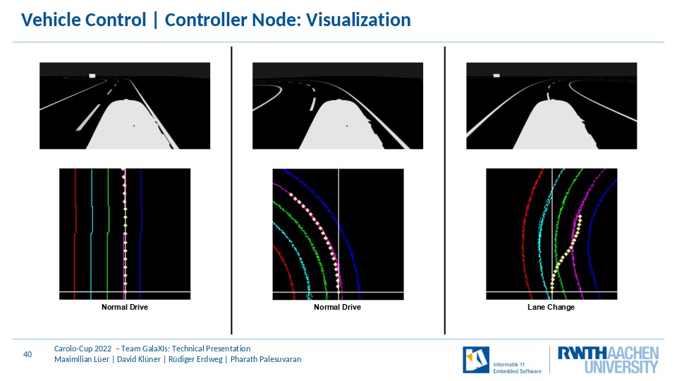
Finally, here you can see the visualization of the environmental model in three situations with the best trajectory that is applied to the car.
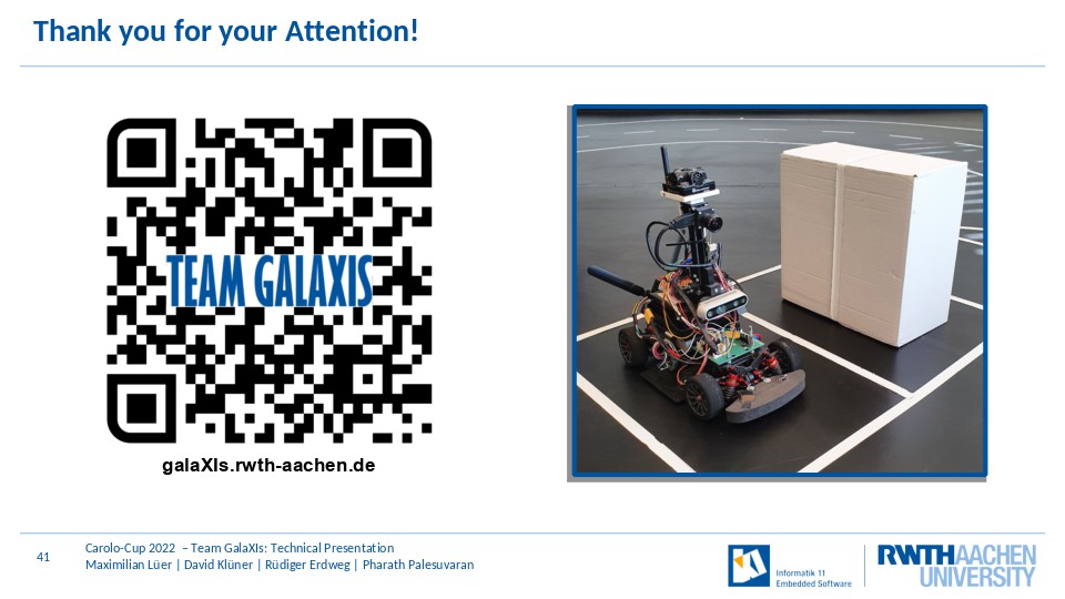
Thank you for your attention!
Appendix (not presented)
Orientation also wiinkel wird angenommen und aber die position
Modell Prädiktive Regelung: Vorausberechnung von zukünftigen Fahrzeugzuständen für die optimale Regelung von zb Geschwindigkeit und Lenkwinkel
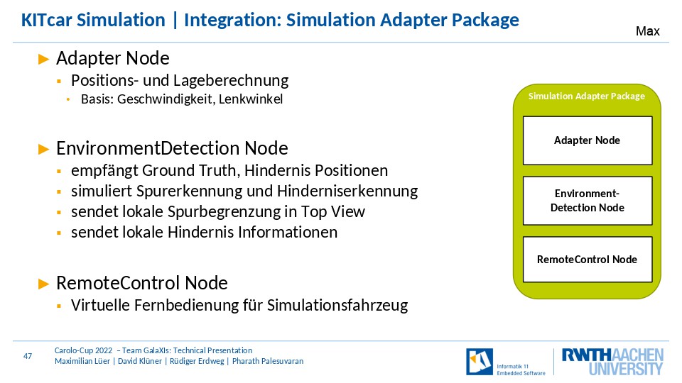
EnvironmentDetection Node: ersetzt Spurerkennung und Hinderniserkennung (parallele Entwicklung)
Screenshot
Switchover is very lowlevel
Nvidia schreibweise
Alternative: tx2 statt agx -> lieber mehr performance fuer headroom
Diese Folie weglassen (potentiell)
- Extract local frontal environment based on current position Hybrid meachanism: Grid Map iterative approach Boundary Polynom-based Shift Approach
Potentiell streichen nicht erwaehnen
Kuerzer
2000 FPS on Ryzen 3900X Modell Prädiktive Regelung: Vorausberechnung von zukünftigen Fahrzeugzuständen für die optimale Regelung von zb Geschwindigkeit und Lenkwinkel Potentiell streichen oder vorher zu sagen